Bar bending schedule-Introduction:
The Bar Bending Schedule (BBS) depicts the bend shapes and cut lengths of bars according to the structural drawings. Because bars are bent in different shapes according on the curvature of the member, each member will have its own BBS.
Basics of Bar Bending Schedule (BBS)
In this article, I will discuss the basics of Bar Bending Schedule, in which I am going to discuss the various sizes of reinforcement bars used. The next topic will be about hooks, in which I will discuss the reasons for providing hooks in structural members, the function of hooks in stirrups, and how to calculate the hook length and cutting length of bend. I’m going to discuss the provision of overlapping reinforcement bars in structural members. The provision of crank bars and how to calculate the cutting length of cranked bars is also included in this article. I’m also going to discuss concrete cover, spacing of reinforcement bars, how to calculate the number of bars, number of stirrups, and at the end, the important discussion will be about the basic steps used to calculate the reinforcement details of a structural member
Diameters of reinforcement bars:

Steel bars come in a variety of sizes, including 6mm, 8mm, 10mm, 12mm, 16mm, 20mm, 25mm, 28mm, 32mm, and 40mm dia. In addition to that, we can have customized diameters that can be ordered directly from the industry as per our needs. The standard length of a steel bar is usually kept as 12m for convenient transportation or this can also be customized as per the bar bending schedule which is usually done in mega projects.
Weight of steel bar:

The weight of a steel bar is calculated by; D2/162 Kg/m ( D is the diameter of the bar)
e.g. if we have a bar of size 8mm its weight in Kg/m will be equal to 82/162 = 0.39Kg/m. Weight per bar = D2/162 x 12(12 is the standard length of steel bar).
Example; weight of 8 mm steel bar = 82/162 x 12 = 4.74Kg/bar.
Why do we provide hooks and how to calculate hook length for bar bending schedule?

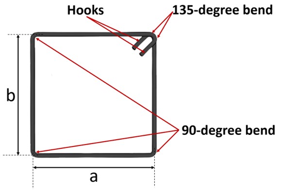
Hooks are provided in structural members as per the need. The function of hooks in stirrups is to prevent seismic movements and to prevent the splitting of concrete. These also keep steel from slipping off the concrete. They hold the steel in position and keep the longitudinal bars in place. The main function of a hook is to develop anchorage.
Why is there a requirement for anchorage?
The tension bars should remain in position, otherwise, their purpose will not be served. So, to develop a bond strength between the steel bars and the concrete, development length requirements must be satisfied. Now there may be chances, where the required length is unavailable to meet the requirements of development length. In those cases, anchorages may be provided in the form of hooks.
Length of hook = 9d, while d is the diameter of the bar
e.g, if we have a bar of length L and the bar is provided with 2 no of hooks on either end. The cutting length of this bar will be equal to the length of bar(L) + hook length (9d + 9d). I.e. Cutting length = L + 9d + 9d
Bend calculation in bar bending schedule:

As you can clearly visualize from the above picture, this steel bar is bent upon either end. These shapes are usually used in footings. The length of this bend is taken from 10d to 16d in which d is the diameter of the bar. The cutting length of this type of bar will be equal to straight length (L) + bends (10d to 12d)
i.e, Cutting length = L + 12d + 12d
OVERLAPPING (LAP LENGTH):

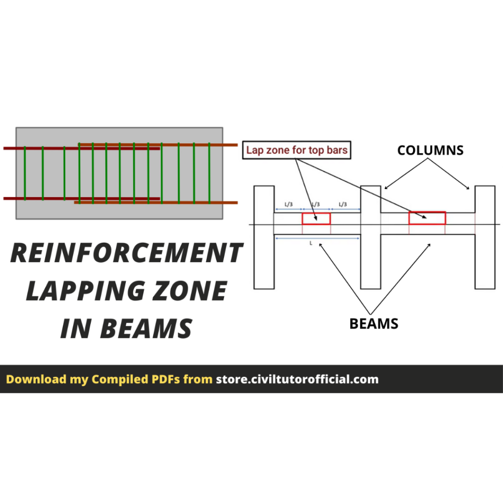
As we know, the standard length of reinforcement bars is 12m. In case we need to increase the span of a structural member like beam or column beyond the standard length of reinforcement bar, which means we also need to increase the length of steel bars by adding more reinforcement bars. If we add the straight bars directly from end to end, then there may be chances of slippage of steel which is prevented by overlapping the bars. The goal of overlapping is to keep the steel bars connected so that the load can be safely transferred from one steel bar to the next. Now the question arises;
What should be the overlapping length?
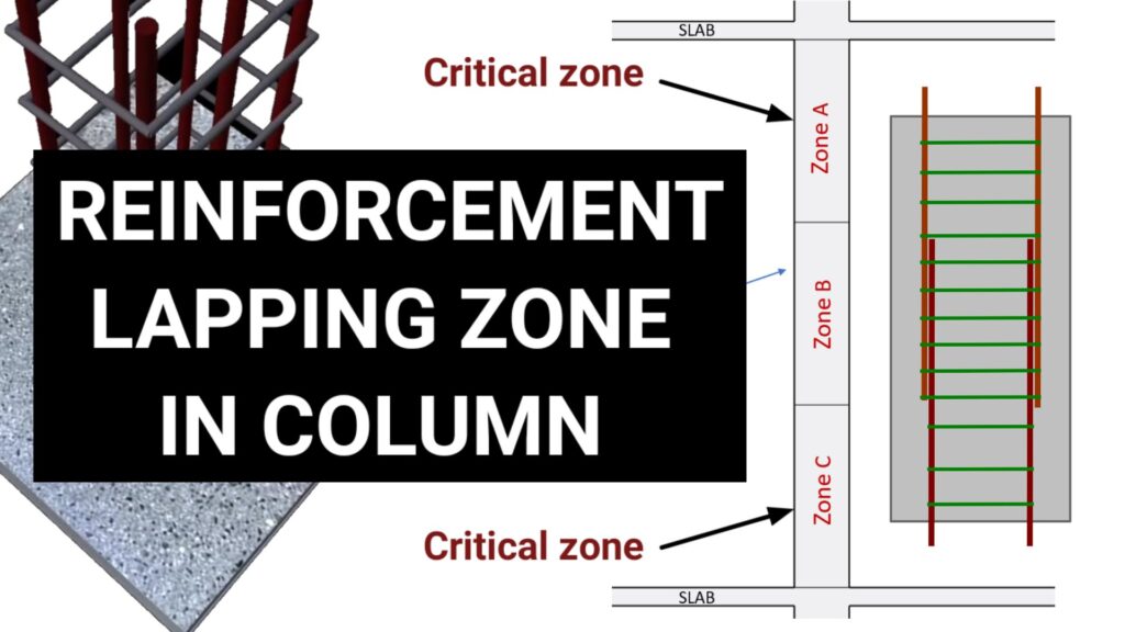
- For compression members (columns) the lap length should be taken as 40d, while d is the diameter of the bar. The reinforcement lapping zone is decided on the basis of critical zone in column. you can read about here
- For tension members (beams) overlapping should be taken as 50d.
But from the practical point of view, we can take 50d for both columns and beams. If we need to overlap the reinforcement from the neck Column to footing, the lap length should be taken as 16d. This length is also known as development length.
CRANK BARS (BENT UP BARS):

Cranked bars are those bars that can resist negative bending moments or simply hogging moments. Bent up bars are provided in slabs as well as in beams since these members are subjected to tensile stresses.

For illustration, I have created a detailed section for a bent-up bar. As you can clearly visualize from this picture. The Inclined length is known as crank length and is equal to 0.42d in which, d = Slab or beam thickness – top and bottom cover
Formula for cutting length of crank bar in bar bending schedule:
Cutting length of cranked bar = L + 0.42d + 0.42d
CONCRETE COVER:

The cover is the space between reinforcement and shuttering or it is the minimum distance between the surface of embedded reinforcement and the outer surface of the concrete. The purpose of providing the concrete cover is to prevent the reinforcement bars from getting corroded by environmental exposure. The concrete cover provides thermal insulation to the steel hence protecting the reinforcement bars from fire.
- Minimum cover for footings is taken as 50mm.
- Minimum cover for Columns & Beams is taken from 25mm to 50mm.
- Minimum cover for Slabs is taken as 25mm.

For illustration, I have shown the cross-section of a beam that is of rectangular shape. The red-colored rectangle is the stirrup and the black colored circles are the main bars. The “concrete cover” is the area between the stirrup and the beam’s outer surface, whereas the exposed concrete surface is the beam’s exterior surface. For providing a clear cover, covering blocks are used to create a space between the reinforcement and the shuttering surface. These blocks are available in different sizes as per the need.
SPACING OF REINFORCEMENT:
Spacing is the distance between two reinforcement bars. The spacing is provided to have a properly anchored reinforcement. That’s why it’s mandatory to cover the steel bars with concrete.
With a 5mm margin between two bars, the minimum distance between them should be at least equal to the aggregate maximum size.
NUMBER OF BARS:
The number of bars is calculated by using the formula, Number of Bars = (opposite length/spacing) + 1

For example, if we have a slab of dimensions Lx x Ly Number of bars along Lx = Ly/spacing + 1
Similarly,
Number of bars along Ly = Lx/spacing + 1
STIRRUPS:


Number of stirrups is calculated by using the formula;
Number of stirrups = (Actual length of column or beam/spacing) +1
STEPS USED IN BAR BENDING SCHEDULE:
- Calculate the length of bar
- Calculate the number of bars
Number of bars = opposite length/spacing + 1
In case we need to calculate the number of stirrups;
Number of stirrups = (actual length of beam or column / spacing) + 1
- Calculate the total length of bars
The total length of Bars = length of bar x number of bars
- Check the diameter of bar used
- Weight per meter of bar is calculated by using the formula;
Weight per meter = D2/162 Kg/m
- Calculate the total weight of bars;
Total weight = Total length of steel calculated x weight per meter.
So these are the basic steps to be followed for the calculation of reinforcement for any structural member.


